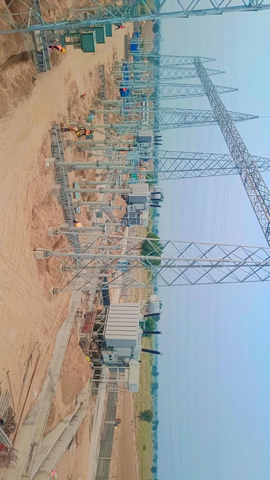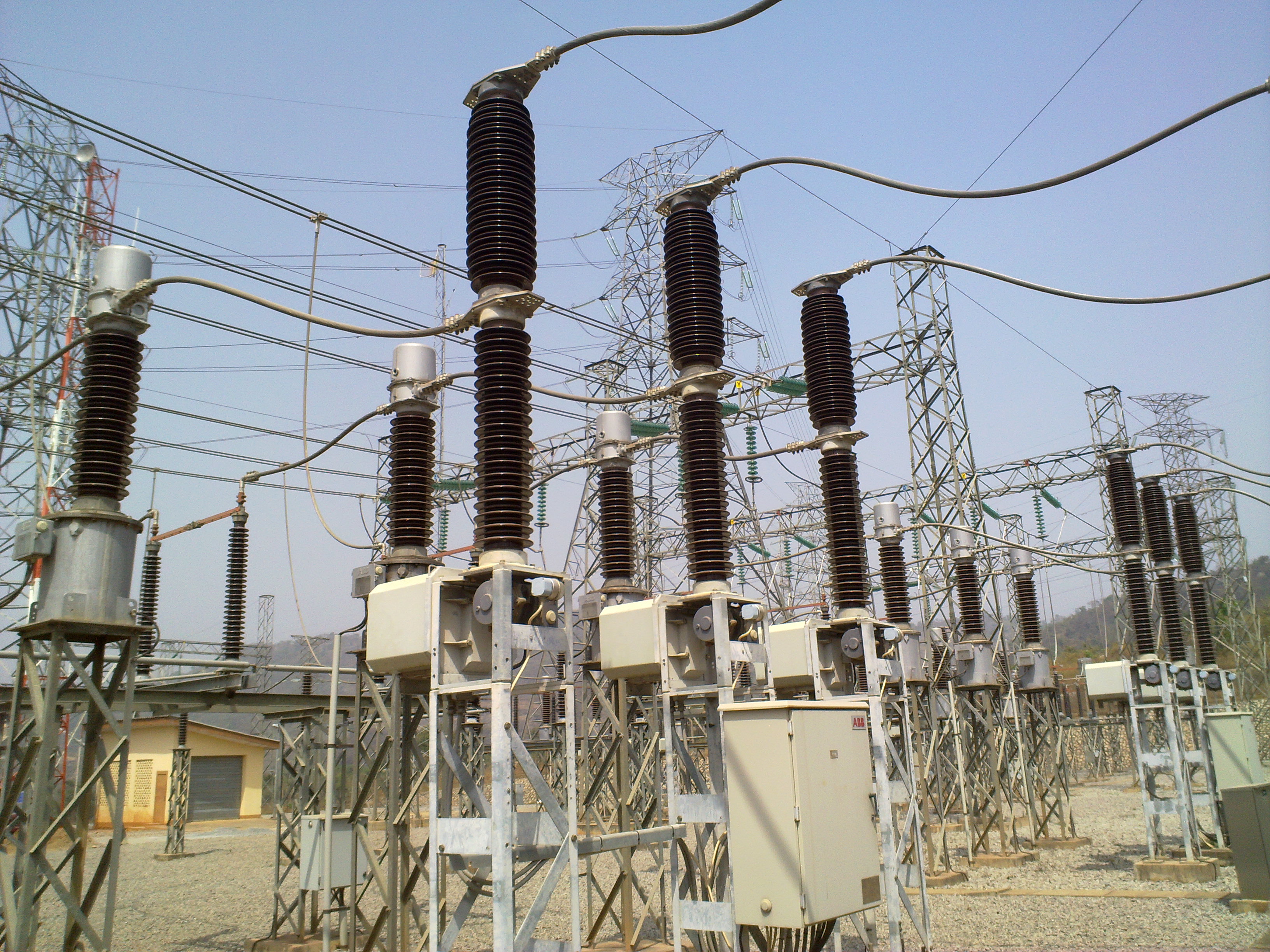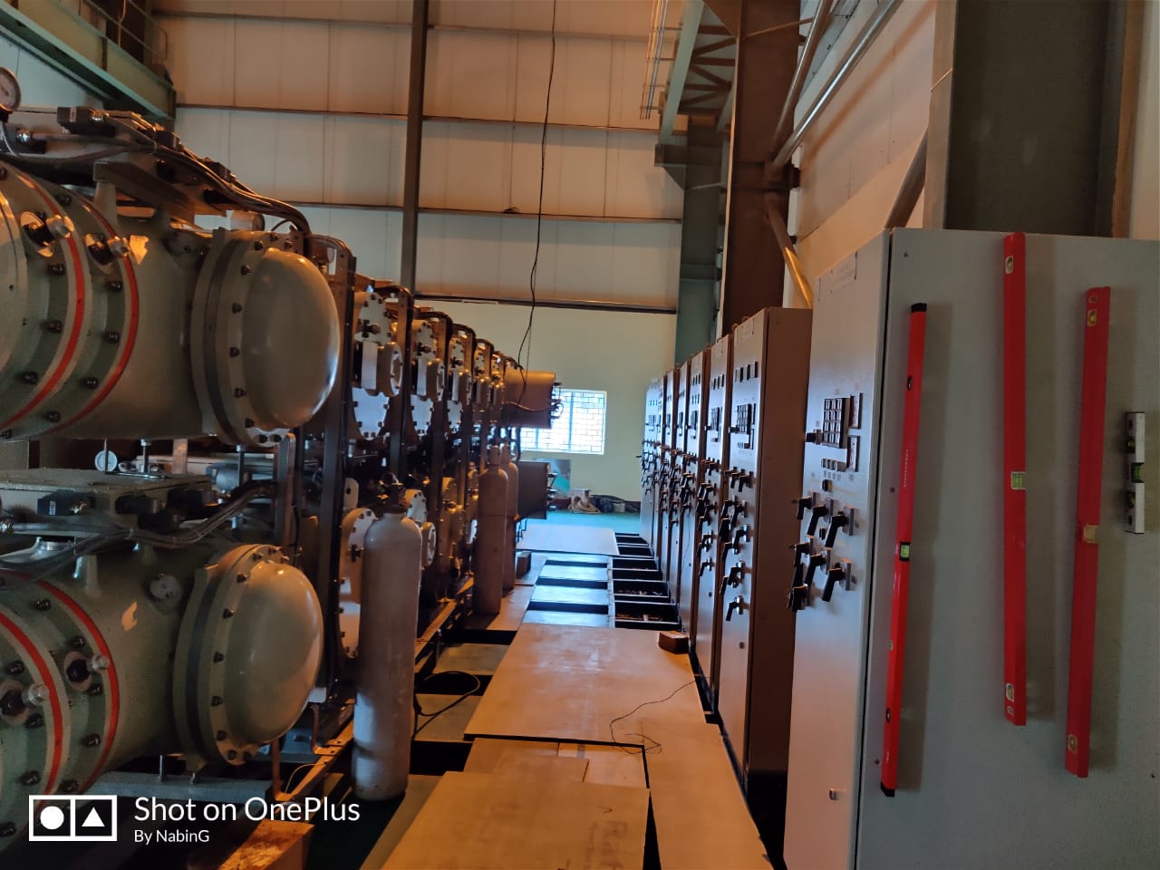


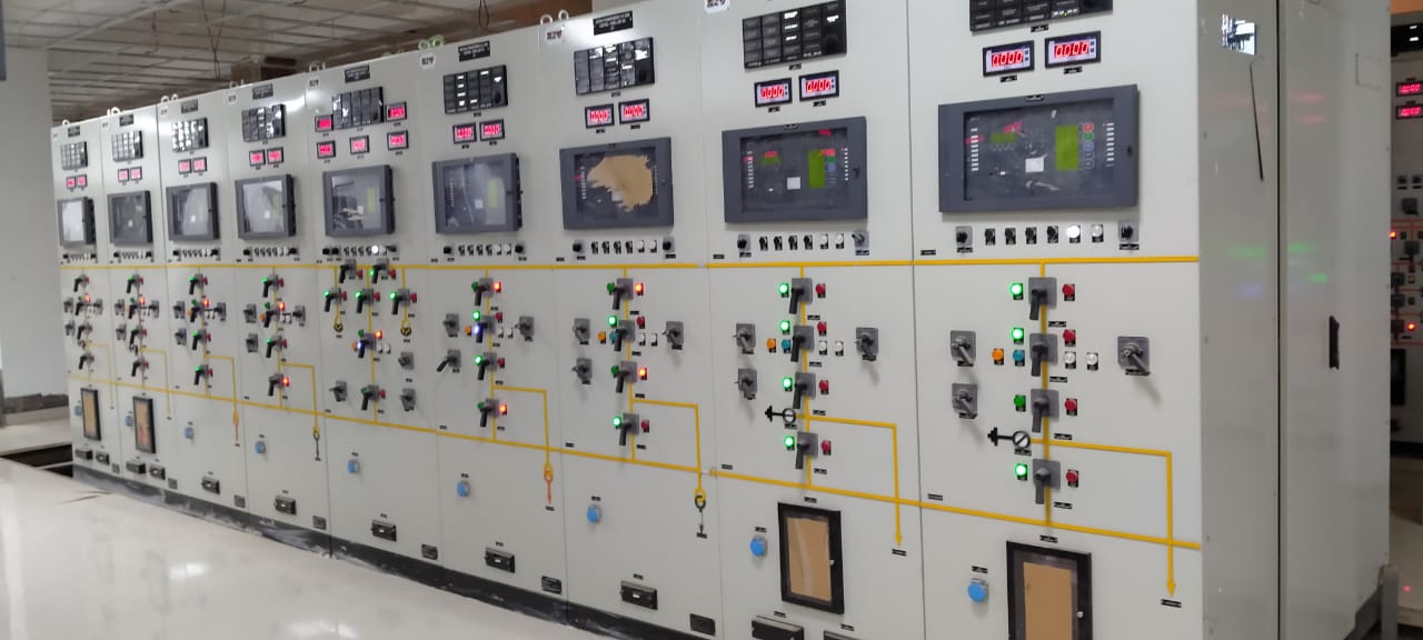


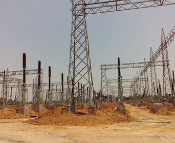


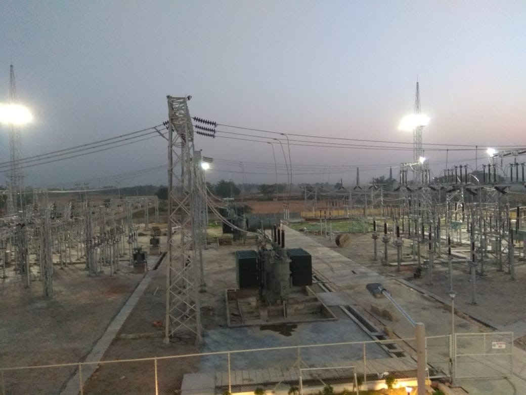
Test completed project
...

| SL. NO. | DESCRIPTION |
| A. | ELECTRICAL DRAWINGS : |
| 1 | SLD |
| 1.1 | Key SLD - 132/33kV Substation |
| 1.2 | 132/33kV Switchyard - Protection & metering SLD |
| 1.3 | SLD - 415V Main Switchboard & ACDB |
| 1.4 | SLD - 415V MLDB & Emergency LDB |
| 1.5 | SLD - 250V DCDB |
| 1.6 | SLD - 48V DCDB |
| 1.7 | SLD - Bay Marshalling Kiosk - 132kV & 33kV |
| 2 | ELECTRICAL LAYOUT & ELEVATION, EKD |
| 2.1 | Switchyard Layout Plan - 132/33kV Substation |
| 2.2 | Switchyard Layout - Elevation of 132/33kV Switchyard |
| 2.3 | Erection key diagram - Plan and Elevation of 132/33kV Switchyard |
| 2.4 | Electrical Equipment Layout with cable trench details - Control Building |
| 3 | CABLE ROUTING, TRAY & TRENCH LAYOUT AND DETAILS |
| 3.1 | Switchyard Cable trench layout and sections with BOM of cable trays |
| 4 | EARTHING LAYOUT & DETAILS |
| 4.1 | Earthing layout & BOM of 132/33kV Switchyard |
| 4.2 | Earthing layout - Control building |
| 4.3 | Earthing layout - DG room |
| 4.4 | Typical Earthing system installation details |
| 5 | LIGHTNING PROTECTION LAYOUT & DETAILS |
| 5.1 | Switchyard DSLP layout and BOM |
| 5.2 | Lightning protection layout with BOM for Control Building |
| 5.3 | Lightning protection layout with BOM for DG room |
| 6 | ILLUMINATION AND SMALL POWER LAYOUT |
| 6.1 | Illumination layout, SLD and BOM - Switchyard and Road |
| 6.2 | Illumination and small power layout, SLD and BOM - Control building |
| 6.3 | Illumination and small power layout, SLD and BOM - Store |
| 6.4 | Illumination and small power layout, SLD and BOM - DG room |
| 6.5 | Illumination and small power layout, SLD and BOM - Pump house |
| 6.6 | Illumination and small power layout, SLD and BOM - Security room |
| 7 | CONTROL SCHEMATICS & BLOCK DIAGRAMS |
| 7.1 | 132KV Intelocking Logic Diagram at BMK |
| 7.2 | 33KV Intelocking Logic Diagram at BMK |
| 8 | CABLE SCHEDULE & INTERCONNECTION DIAGRAMS |
| 8.1 | 132kV switchyard - Control Cable schedule and Interconnection Diagrams |
| 8.2 | 33kV switchyard - Control Cable schedule and Interconnection Diagrams |
| 8.3 | LV Switchgear, ACDB, DCDB, MLDB, ELDB, SLDBs, BMK - Power Cable Schedule and Interconnection Diagram |
| B. | ELECTRICAL DESIGN CALCULATIONS |
| 1 | 132/33kV Switchyard - Earthing calculation |
| 2 | 132/33kV Switchyard DSLP calculation |
| 3 | Lighting calculation - Control Building and other buildings |
| 4 | Lighting calculation - 132/33kV switchyard and Road |
| C. | STRUCTURAL DRAWINGS WITH BOM AND WEIGHT AND DESIGN CALCULATIONS : |
| C.1 | 132KV : |
| 1 | GA drawing of 132kV Line gantry tower |
| 2 | GA drawing of 132kV Line gantry beam |
| 3 | GA drawing of 132kV Transformer gantry tower |
| 4 | GA drawing of 132kV Transformer gantry beam |
| 5 | GA drawing of 132kV Main bus A-Frame structure |
| 6 | GA drawing of 132kV Transfer bus A-Frame structure |
| 7 | GA drawing of support structure for 132kV Isolator with E/S |
| 8 | GA drawing of support structure for 132kV Isolator without E/S |
| 9 | GA drawing of support structure for 132kV Tandem Isolator |
| 10 | GA drawing of support structure for 132kV LA |
| 11 | GA drawing of support structure for 132kV CVT |
| 12 | GA drawing of support structure for 132kV CT |
| 13 | GA drawing of support structure for 132kV BPI |
| 14 | GA drawing of support structure for 132kV PT |
| 15 | GA drawing of 40m lightning mast |
| C.2 | 33KV : |
| 1 | GA drawing of 33kV Line gantry tower |
| 2 | GA drawing of 33kV Line gantry beam |
| 3 | GA drawing of 33kV Transformer gantry tower |
| 4 | GA drawing of 33kV Transformer gantry beam |
| 5 | GA drawing of 33kV Main bus A-Frame structure |
| 6 | GA drawing of 33kV Transfer bus A-Frame structure |
| 7 | GA drawing of support structure for 33kV Isolator with E/S |
| 8 | GA drawing of support structure for 33kV Isolator without E/S |
| 9 | GA drawing of support structure for 33kV LA |
| 10 | GA drawing of support structure for 33kV PT |
| 11 | GA drawing of support structure for 33kV CT |
| 12 | GA drawing of support structure for 33kV BPI (Low level) |
| 13 | GA drawing of support structure for 33kV BPI (High level) |
| 14 | GA drawing of support structure for 33kV HG fuse |
| C.3 | STRUCTURAL DESIGN CALCULATIONS : |
| 1 | Structural design calculations - 132kV |
| 2 | Structural design calculations - 33kV |
| D. | CIVIL CONSTRUCTIONAL DRAWINGS AND DESIGN CALCULATIONS : |
| D.1 | GENERAL : |
| 1 | Overall foundation layout of switchyard |
| 2 | Foundation details of Lightning mast |
| 3 | Foundation design calculations for lightning mast |
| D.2 | 132KV GANTRY TOWER AND EQUIPMENT FOUNDATION DETAILS : |
| 1 | Foundation details of 132kV Line, Transformer and Bus gantry tower |
| 2 | Foundation details of support structure for 132kV Equipment |
| 3 | Foundation design calculations |
| D.3 | 33KV GANTRY TOWER AND EQUIPMENT FOUNDATION DETAILS : |
| 1 | Foundation details of 33kV Line, Transformer and Bus gantry tower |
| 2 | Foundation details of support structure for 33kV Equipment |
| 3 | Foundation design calculations |
| D.4 | CIVIL CONSTRUCTIONAL DETAILS AND ARCHITECTURAL DETAILS OF CONTROL BUILDING: |
| 1 | Architectural layout plan, elevation and details for Control building |
| 2 | Control Building - GA of Foundation, Column, Trenches & RC Details |
| 3 | GA of Control Building Plinth Beam Layout and Details |
| 4 | Control Building - Roof Beam layout and Details |
| 5 | Control Building - RC Details of Roof Slab |
| 6 | Control Building - Layout and RC Details of Lintel Beams, stair case & Miscellaneous Details |
| 7 | Constructional details of septic tank and soak pit |
| 8 | Sanitary and plumbing details |
| 9 | RCC Design calculations for Control building |
| 10 | Design calculation for septic tank and soak pit |
| D.5 | OTHER CIVIL CONSTRUCTIONAL DETAILS : |
| 1 | 50MVA Transformer foundation and oil pit |
| 2 | Common oil pit for 50MVA Transformer |
| 3 | 315KVA Transformer foundation |
| 4 | Outdoor cable trench and trench cover slab |
| 5 | Switchyard area drainage system layout and details |
| 6 | Boundary wall with retaining wall |
| 7 | Main entrance gate |
| 8 | Fence and fence gate |
| 9 | Switchyard internal roads |
| 10 | Water sump and dewatering pump |
| 11 | Foundation of street lighting poles |
| 12 | Details of land development, cutting, filling and levelling |
| 13 | Construction of DG room, Security and Store building |
| 14 | Construction of Security post |
| 15 | Construction of Store building |
| D.6 | MISC. CIVIL DESIGN CALCULATIONS |
| 1 | Design calculation for 50MVA Transformer foundation |
| 2 | Design calculation for common oil pit for 50MVA Transformer |
| 3 | Design calculation for 315KVA Transformer foundation |
| 4 | Design calculation for outdoor cable trench and cover slab |
| 5 | Design calculation for Switchyard area drainage system |
| 6 | Design calculation for road construction |
| 7 | Design calculation for construction of DG room, store shed and security room |
| 8 | Design calculation for construction of boundary wall with retaining wall |
| 9 | Design calculation for land development, cutting, filling and levelling |
| E. | OTHER SERVICES : |
| 1 | Vendor drawing review and approval for 132/33kV Control & Relay panels, PLCC systems |
| 2 | Survey of substation plot and preparation of topographical contour layout drawings |
| 3 | Geotechnical investigation of substation plot consisting of SBC test, Soil resistivity and CBR tests |