


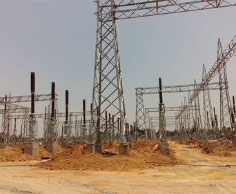


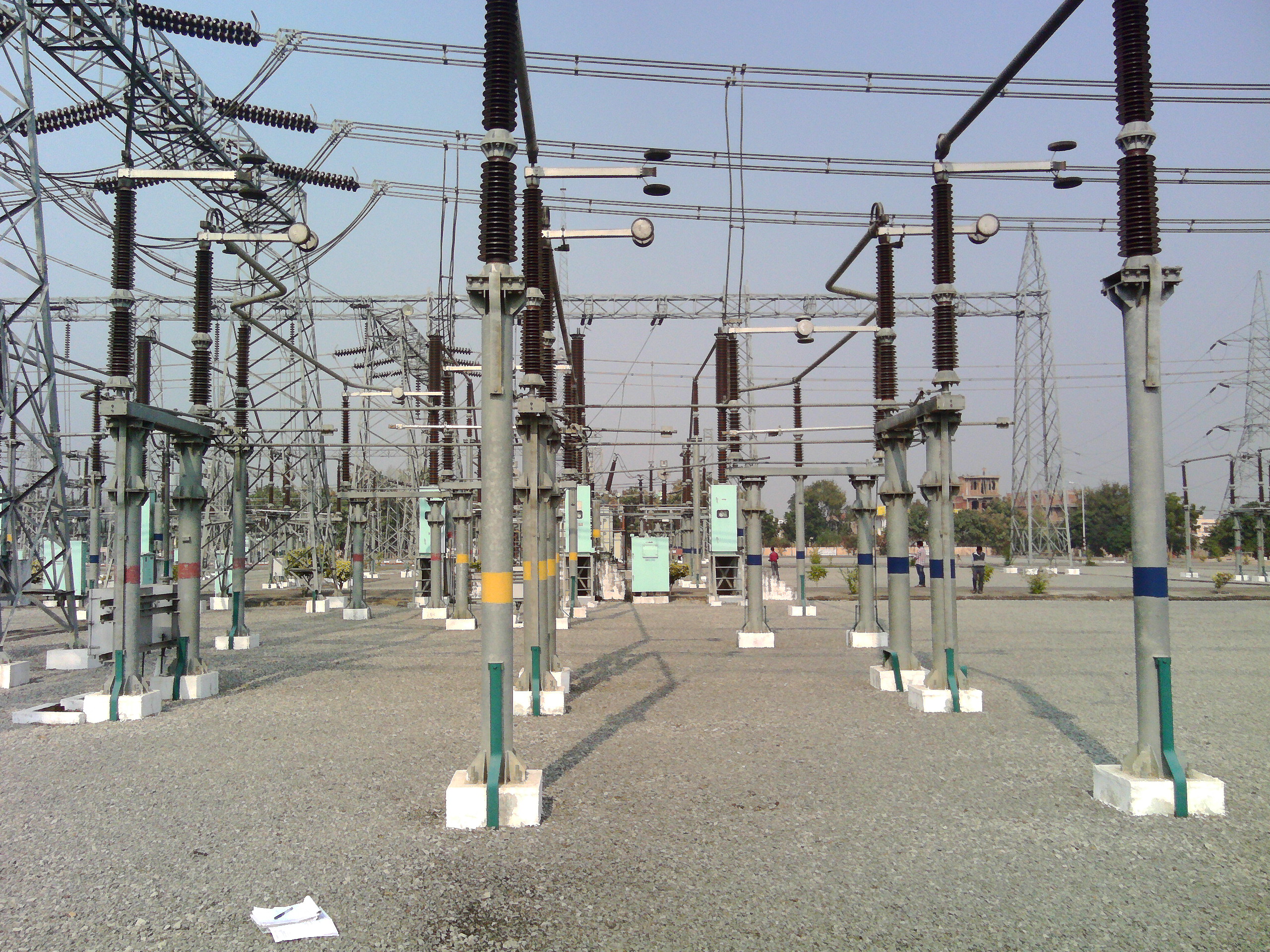
Test completed project
...

| SL. NO. | DESCRIPTION |
| A. | ELECTRICAL DRAWINGS : |
| 1 | SLD |
| 1.1 | Key SLD - 400/220/33kV Transformer bay extension and 400kV Bus reactor |
| 1.2 | Protection and metering SLD of 400/220/33kV Transformer bay extension |
| 1.3 | Protection and metering SLD of 400kV Bus reactor |
| 1.4 | Protection and metering SLD of 33kV Tertiary loading system |
| 1.5 | SLD - Extension of 415V ACDB |
| 1.6 | SLD - 415V Lighting distribution |
| 1.7 | SLD - Extension of 220V DCDB |
| 1.8 | SLD - Bay Marshalling Kiosk - 400kV |
| 1.9 | SLD - Bay Marshalling Kiosk - 33kV |
| 1.10 | SLD - 415V Sub ACDB at 400kV Switchyard panel room |
| 1.11 | SLD - 220V Sub DCDB at 400kV Switchyard panel room |
| 1.12 | Overall SLD of LV AC & DC distribution |
| 2 | ELECTRICAL LAYOUT & ELEVATION, EKD |
| 2.1 | 400kV Switchyard Layout - Plan and Elevation |
| 2.2 | 400kV Switchyard Layout - Elevation |
| 2.3 | 220kV Switchyard Layout - Plan & Elevation |
| 2.4 | 33kV Switchyard layout - Plan & Elevation |
| 2.5 | 400kV Switchyard - Erection key diagram - Plan & Elevation |
| 2.6 | AL Tube cut length schedule |
| 2.7 | Electrical Equipment Layout with cable trench details - Control Building |
| 2.8 | Electrical Equipment Layout with cable trench details - 400kV Switchyard panel room |
| 2.9 | 400kV Switchyard - Clearance Diagram - Plan & Elevation |
| 3 | CABLE ROUTING, TRAY & TRENCH LAYOUT AND DETAILS |
| 3.1 | 400/220/33kV Switchyard - Cable trench layout and sections |
| 3.2 | Cabling Notes and cable tray details |
| 4 | EARTHING LAYOUT & DETAILS |
| 4.1 | 400/220/33kV Switchyard - Earthing layout |
| 4.2 | Earthing layout - Control building |
| 4.3 | Earthing layout - 400kV Switchyard panel room |
| 4.4 | Earthing Notes & Details |
| 5 | LIGHTNING PROTECTION LAYOUT & DETAILS |
| 5.1 | 400/220/33kV Switchyard DSLP layout |
| 6 | ILLUMINATION AND SMALL POWER LAYOUT |
| 6.1 | 400/220/33kV Switchyard - Illumination layout and SLD |
| 6.2 | Illumination and small power layout, SLD - Switchyard roads |
| 6.3 | Illumination and small power layout, SLD - 400KV Switchyard panel room |
| 6.4 | Lighting Notes & Details |
| 7 | CONTROL SCHEMATICS & BLOCK DIAGRAMS |
| 7.1 | 400/220KV BMK intelocking scheme and wiring diagram |
| 8 | CABLE SCHEDULE & INTERCONNECTION DIAGRAMS |
| 8.1 | Control Cable schedule and Interconnection Diagrams for 400kV, 220kV & 33kV bays |
| 8.2 | 220kV switchyard - Control Cable schedule and Interconnection Diagrams |
| 8.3 | 33kV switchyard - Control Cable schedule and Interconnection Diagrams |
| 8.4 | LV Switchgear, ACDB, DCDB, LDB, BMK - Power Cable Schedule and Interconnection Diagram |
| 9 | SCADA |
| 9.1 | SCADA I/O List |
| 9.2 | Schematic Block diagram for integration of new bays with existing SCADA system |
| 10 | BOQ |
| 10.1 | Clamps, connectors, hardwares, conductor, Al. tube bus |
| 10.2 | Earthing material |
| 10.3 | Cable trays |
| 10.4 | Lighting material |
| 10.5 | Power and control cables |
| 10.6 | Cabling material |
| 10.7 | SCADA system |
| B | ELECTRICAL DESIGN CALCULATIONS |
| 1 | 400/220/33kV Switchyard DSLP calculation |
| 2 | Lighting calculation - 400kV switchyard |
| 3 | Lighting calculation - Switchyard roads |
| 4 | Lighting calculation - 400kV Switchyard panel room |
| 5 | Bus bar design calculation |
| 6 | Short circuit force calculation for Rigid tubular bus - Verification of BPI Strength and critical span calculation |
| 7 | Sag & Tension Calculation |
| 8 | PS class CT Vk sizing calculation |
| 9 | LV power cable sizing calculation |
| C | STRUCTURAL DRAWINGS WITH BOM AND WEIGHT AND DESIGN CALCULATIONS : |
| C.1 | 400KV (Modification of standard structures) : |
| 1 | Overall structural layout of 400/220/33kV switchyard |
| 2 | Overall structural layout (elevation) of 400/220/33kV switchyard |
| 3 | GA drawing of support structure for 400kV Isolator with E/S |
| 4 | GA drawing of support structure for 400kV LA |
| 5 | GA drawing of support structure for 400kV CVT |
| 6 | GA drawing of support structure for 400kV CT |
| 7 | GA drawing of support structure for 400kV BPI |
| C.2 | 220KV (Modification of existing structures) : |
| 1 | GA drawing of support structure for 220kV Isolator with E/S |
| 2 | GA drawing of support structure for 220kV Isolator without E/S |
| 3 | GA drawing of support structure for 220kV LA |
| 4 | GA drawing of support structure for 220kV CVT |
| 5 | GA drawing of support structure for 220kV CT |
| 6 | GA drawing of support structure for 220kV BPI |
| C.3 | STRUCTURAL DESIGN CALCULATIONS : |
| 1 | Structural design calculations - 400kV |
| 2 | Structural design calculations - 220kV |
| D | CIVIL CONSTRUCTIONAL DRAWINGS AND DESIGN CALCULATIONS : |
| 1 | Geotechnical investigation plan drawing showing locations of bore holes, soil resistvity, CBR test locations |
| 2 | Oil water separator pit for 500MVA Transformer |
| 3 | Details of oil drain pipe for 500MVA Transformer |
| 4 | 1000KVA Transformer foundation |
| 5 | Extension of cable trench at existing control building |
| 6 | Outdoor drainage layout |
| 7 | Fence layout, details and fence gate |
| 8 | Rail cum road |
| 9 | Overall foundation layout |
| CIVIL DESIGN CALCULATIONS | |
| 1 | Design calculation for oil water separator pit for 500MVA Transformer |
| 2 | Design calculation for 1000KVA Transformer foundation |
| 3 | Design calculation for outdoor drainage system |
| 4 | Design calculation for rail cum road construction |
| 5 | BOQ of complete civil works |
| E | FIRE PROTECTION SYSTEM |
| 1 | P&I diagram of the fire protection system |
| 2 | Extension of fire hydrant piping layout in the switchyard |
| 3 | HVW spray system for Transformer (plan, elevation, side view, isometric view and pylon support details) |
| 4 | Pylon support locations |
| 5 | Hydraulic calculation for HVW spray network for Transformer /Reactor |
| 6 | BOQ of Fire protection system |
| F | AIR CONDITIONING SYSTEM |
| 1 | Air conditioning system layout of Switchyard panel room |
| 2 | Design calculation for Air conditioning system of Switchyard panel room |
| 3 | BOQ of Air conditioning system |