


Test completed project
...


Scope of Work :
| SL. NO. | DESCRIPTION |
| A. | ELECTRICAL DRAWINGS : |
| 1 | SLD |
| 1.1 | Key SLD |
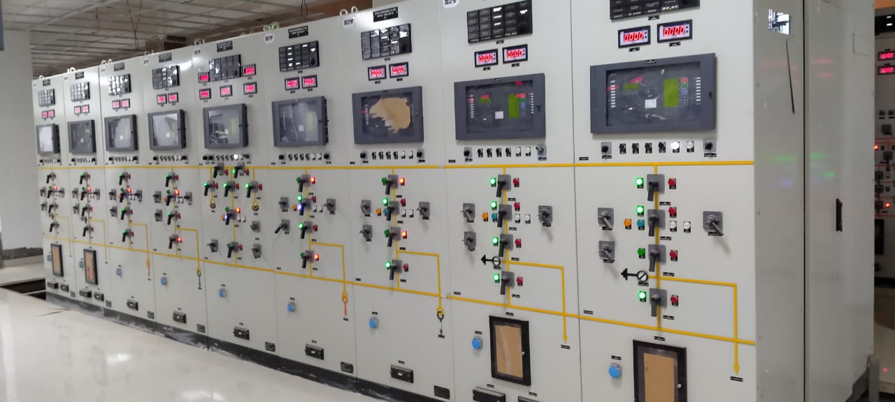
| 1.2 | 132kV Line - Protection & Metering SLD |
| 1.3 | SLD - 415V Bay Marshalling Kiosk for 132 kV Line |
| 1.4 | SLD - 415V Main ACDB |
| 1.5 | SLD - 220V DCDB |
| 2 | ELECTRICAL LAYOUT & ELEVATION, EKD |
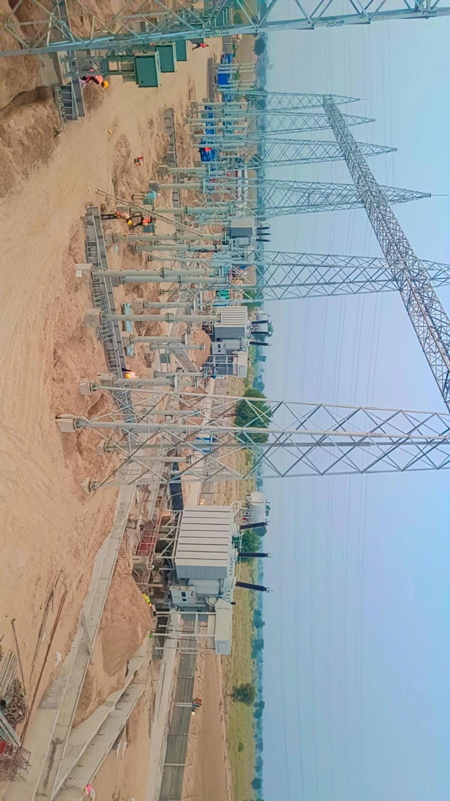
| 2.1 | 132kV Switchyard Layout - Plan & Elevation |
| 2.2 | 132kV Switchyard - Erection key diagram -Plan & Elevation |
| 2.3 | Equipment and Cable trench layout of Control room extension |
| 3 | CABLE ROUTING, TRAY & TRENCH LAYOUT AND DETAILS |
| 3.1 | Cable Trench Layout and BOM of Cable Trays, racks for the 132kV line bay extension |
| 4 | EARTHING LAYOUT & DETAILS |
| 4.1 | Earthing Layout and BOM for the 132kV line bay extension |
| 4.2 | Earthing layout and BOM of Control room extension |
| 5 | LIGHTNING PROTECTION LAYOUT & DETAILS |
| 5.1 | Lightning Protection Layout and BOM for the 132kV line bay extension |
| 5.2 | Lightning Protection Layout and BOM for Control room extension |
| 6 | LIGHTING LAYOUT & DETAILS |
| 6.1 | Lighting Layout and BOM for the 132kV line bay extension |
| 6.2 | Lighting layout and BOM of Control room extension |
| 7 | CONTROL SCHEMATICS & BLOCK DIAGRAMS |
| 7.1 | 132 kV Interlocking Logic Diagram at BMK |
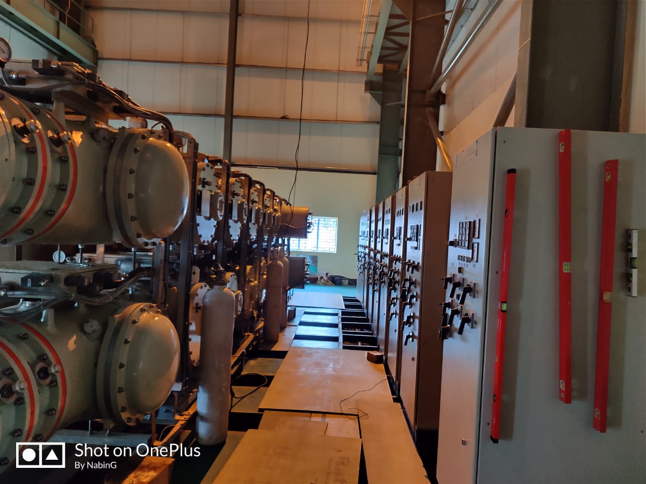
| 7.2 | Block architecture for new PLCC system and interfacing with existing PLCC, EPAX |
| 7.3 | Block architecture for interfacing with existing SCADA system |
| 7.4 | 132kV CT/CVT/PT JB terminal plan |
| 8 | CABLE SCHEDULE & INTERCONNECTION DIAGRAMS |
| 8.1 | Control Cable Schedule and Interconnection Diagram |
| 8.2 | LV Power Cable Schedule and Interconnection Diagram |
| 8.3 | Instrument cable schedule for interconnection of the line bay extension with existing SAS and Meter reading console. |
| B. | ELECTRICAL DESIGN CALCULATIONS : |
| 1 | Earthing calculation of 132kV line bay extension |
| 2 | Lightning protection calculation for 132kV line bay extension |
| 3 | Lightning protection calculation for the control room extension |
| 4 | 220V Battery sizing calculation |
| 5 | 220V Battery charger sizing calculation |
| 6 | 132kV CT & CVT/PT sizing calculation |
| 7 | Lighting calculation for Switchyard |
| 8 | Lighting calculation for Control room extension |
| 9 | Short circuit force calculation on ACSR conductor for steel structure design |
| 10 | Sag & tension calculation in ACSR conductor |
| C. | CIVIL DRAWINGS : |
| 1 | Foundation Details of all Support Structure : |
| 1.01 | 132kV LA |
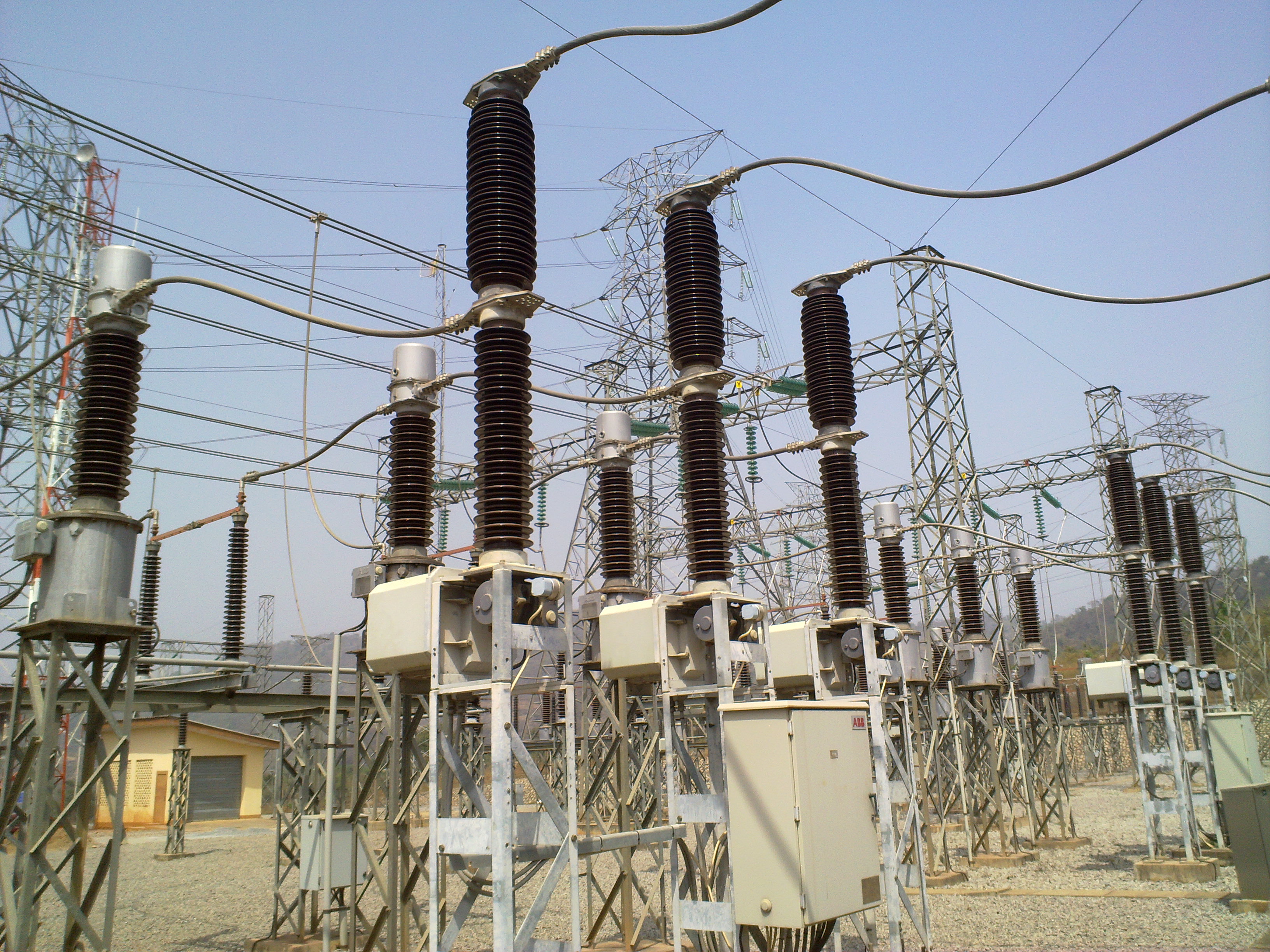
| 1.02 | 132kV CT |
| 1.03 | 132kV PT |
| 1.04 | 132kV CVT |
| 1.05 | 132kV Isolator |
| 1.06 | 132kV Tandem Isolator |
| 1.07 | 132kV CB |
| 1.08 | 132kV Post Insulator (1 PH.) |
| 1.09 | 132kV Line Gantry Tower |
| 1.10 | 132kV Bus Gantry Tower |
| 1.11 | Construction Details of Outdoor Cable Trenches |
| 1.12 | Overall foundation layout for Line Bay Extension |
| 1.13 | Civil and Architectural drawings for Control building extension |
| 1.14 | Drainage system layout and constructional details |
| D. | CIVIL DESIGN CALCULATIONS : |
| 1 | Design Calculation for Equipment and Tower Foundations |
| 2 | Design Calculation for Cable Trenches |
| 3 | Design calculation for Control building extension |
| E. | STRUCTURE DRAWINGS : |
| 1 | GA of Structures including BOM and Weight of each individual member for : |
| 1.1 | 132kV Normal Isolator |
| 1.2 | 132kV Tandem Isolator |
| 1.3 | 132kV CT |
| 1.4 | 132kV PT |
| 1.5 | 132kV LA |
| 1.6 | 132kV P.I - single phase |
| 1.7 | 132kV Line Gantry Tower |
| 1.8 | 132kV Line Gantry Beam |
| 1.9 | 132kV CVT |
| 1.10 | 132kV Bus Gantry Tower with peak |
| 1.11 | 132kV Bus Gantry Tower without peak |
| 1.12 | 132kV Bus Gantry Beam |
| F. | STRUCTURE DESIGN CALCULATION : |
| 1 | Design Calculation for Tower & Equipment support structures |