


Test completed project
...


Scope of work :
The scope included site visit, data collection, discussion with Client and submission of the following detail engineering drawings :
| SL. NO. | DESCRIPTION |
| A. | DRAWINGS : |
| 1 | SLD |
| 1.1 | 400kV Switchyard - Protection & metering SLD (Power Plant End) |
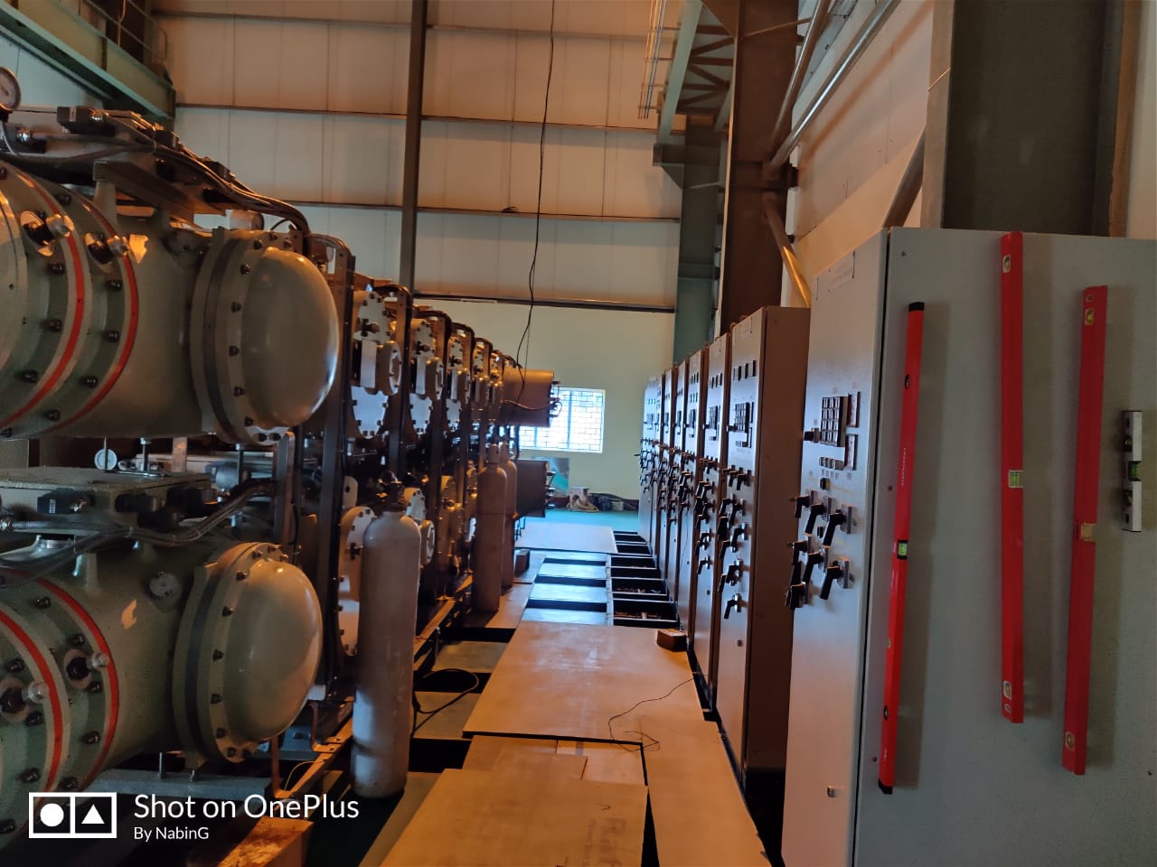
| 1.2 | 33kV Switchyard - Protection & metering SLD |
| 1.3 | SLD - DCDB |
| 1.4 | SLD - ACDB |
| 1.5 | SLD - MLDB |
| 1.6 | SLD - 415V PCC |
| 1.7 | SLD - Marshalling Kiosk |
| 2 | ELECTRICAL LAYOUT & ELEVATION, EKD |
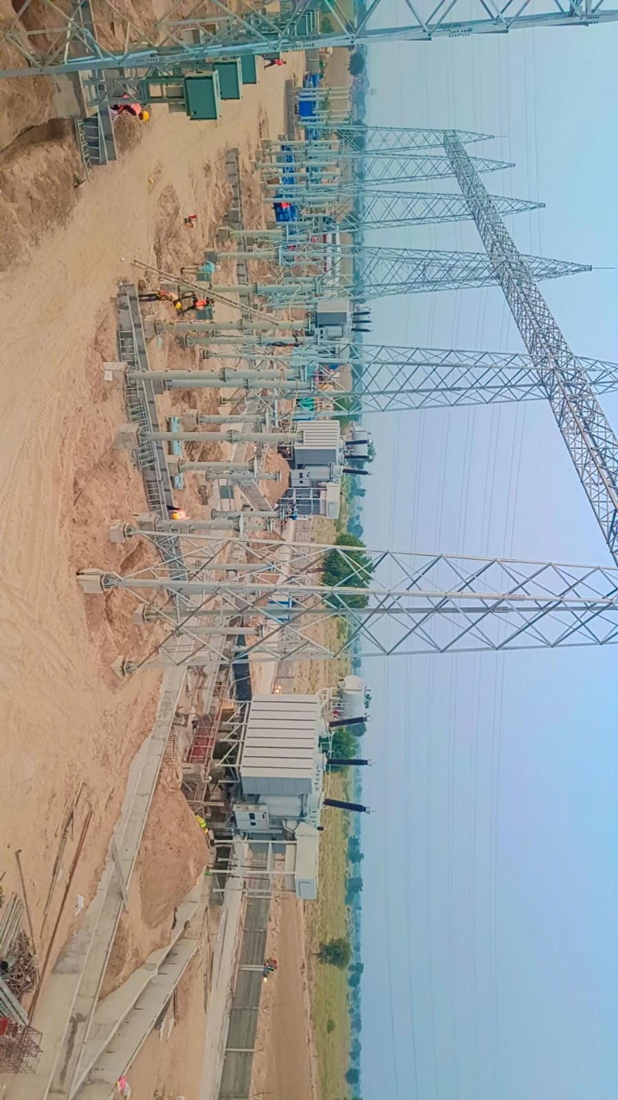
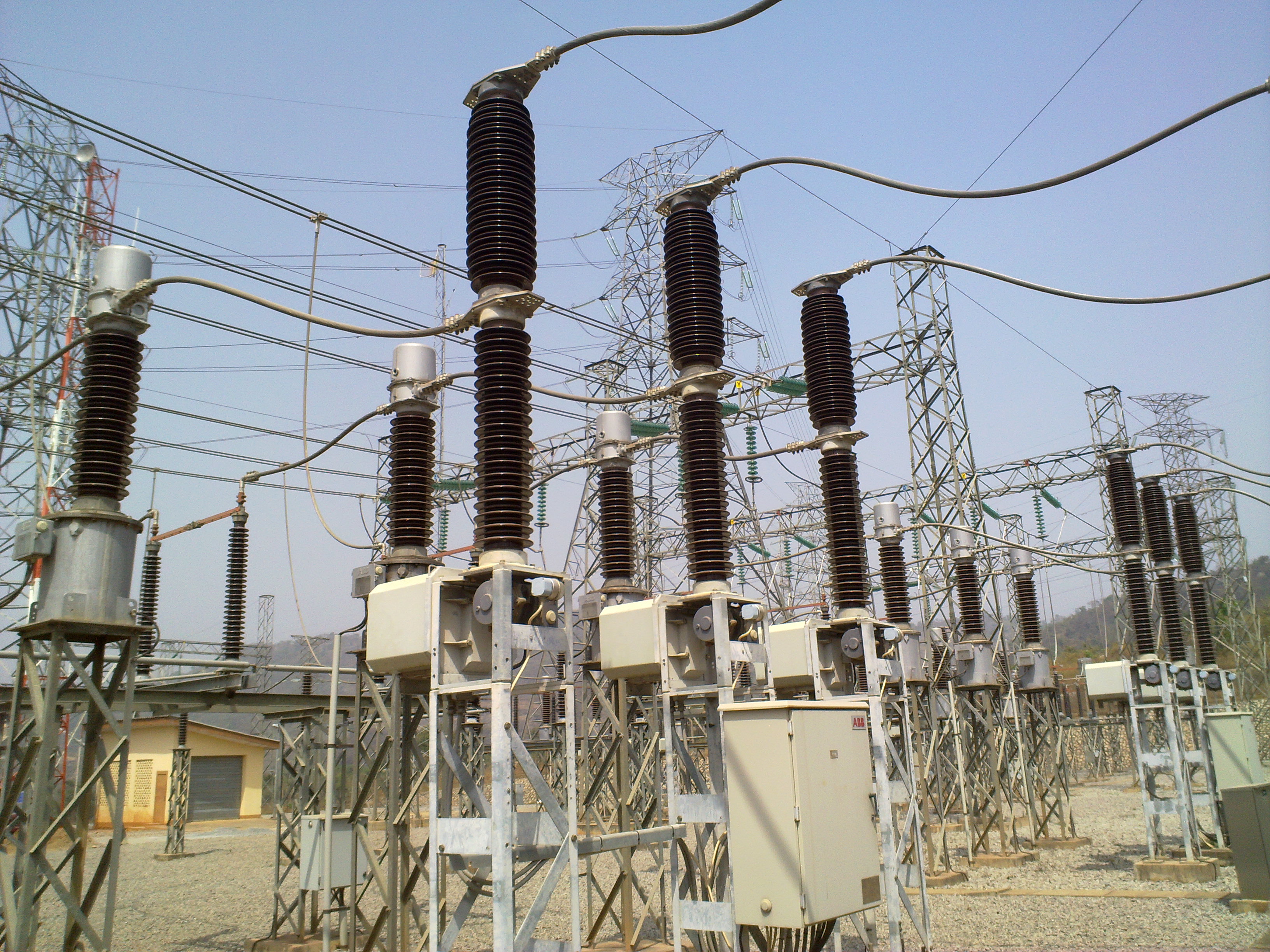
| 2.1 | 400kV Switchyard Layout - Plan (Power Plant End) |
| 2.2 | 400kV Switchyard Layout - Section (Power Plant End) |
| 2.3 | 400kV Switchyard - Erection key diagram - plan (Power Plant End) |
| 2.4 | 400kV Switchyard - Erection key diagram - section (Power Plant End) |
| 2.5 | 33kV Switchyard Layout - Plan & section |
| 2.6 | 33kV Switchyard - Erection key diagram - plan & section |
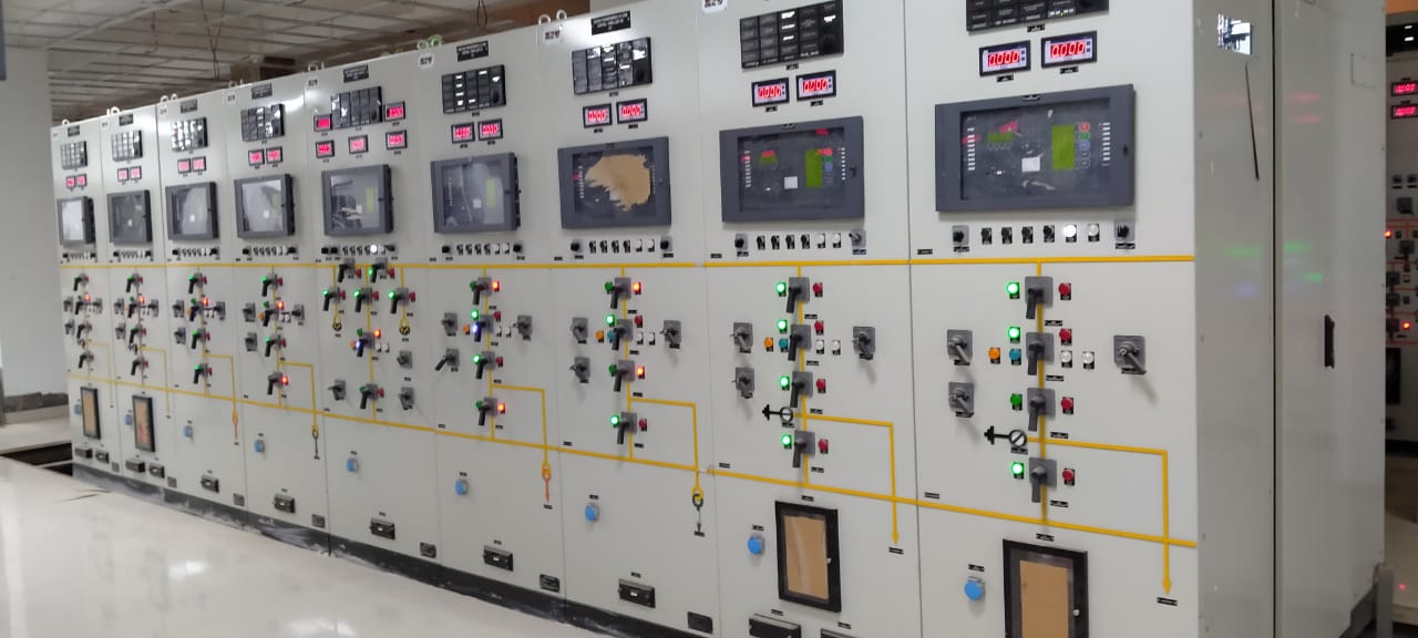
| 2.7 | Electrical equipment layout - control building |
| 2.10 | Electrical equipment layout - air conditioned bay marshalling kiosks |
| 3 | CABLE ROUTING, TRAY & TRENCH LAYOUT AND DETAILS |
| 3.1 | 400kV Switchyard - Cable trench layout and sections (Power Plant End) |
| 3.2 | 33kV Switchyard - Cable trench layout and sections |
| 3.3 | Cable tray, trench Layout & Sections - Control Building |
| 3.4 | Cable tray, trench Layout & Sections - Air conditioned bay marshalling kiosks |
| 4 | EARTHING LAYOUT & DETAILS |
| 4.1 | 400/33kV Switchyard - Earthing layout (Power Plant End) |
| 4.2 | Earthing layout - Control building |
| 4.3 | Earthing layout - Air conditioned bay marshalling kiosk |
| 4.4 | Earthing Notes & Details |
| 5 | LIGHTNING PROTECTION LAYOUT & DETAILS |
| 5.1 | 400kV Switchyard DSLP layout (Power plant end) |
| 5.2 | 33kV Switchyard DSLP layout |
| 5.3 | Lightning protection layout - Control Building |
| 5.4 | Lightning Protection Notes & Details |
| 6 | ILLUMINATION LAYOUT |
| 6.1 | 400kV Switchyard - Illumination layout, SLD and BOM (Power plant end) |
| 6.2 | 33kV Switchyard - Illumination layout, SLD and BOM |
| 6.3 | Illumination layout, SLD and BOM - Control building |
| 6.4 | Lighting Notes & Details |
| 7 | CONTROL SCHEMATICS |
| 7.1 | 400KV Intelocking Logic Diagram |
| 7.2 | 33KV Intelocking Logic Diagram |
| 7.3 | Control cabling block diagrams - 400kV |
| 7.4 | Control cabling block diagrams - 33kV |
| 8 | CABLE SCHEDULE & INTERCONNECTION DIAGRAMS |
| 8.1 | 400kV switchyard - Power and control Cable schedule and Interconnection Diagrams (Power plant end) |
| 8.2 | 33kV switchyard - Power and control Cable schedule and Interconnection Diagram |
| 8.3 | 415V PCC - Power and Control Cable Schedule and Interconnection Diagrams |
| 8.4 | ACDB, DCDB - Power Cable Schedule and Interconnection Diagram |
| B | DESIGN CALCULATIONS |
| 1 | Strung bus short circuit force calculation (Power plant end) |
| 2 | Sag-tension calculation of strung bus (Power plant end) |
| 3 | Rigid bus short circuit force and span calculation (Power plant end) |
| 4 | 400/33kV Switchyard - Earthing calculation (Power Plant End) |
| 5 | 400kV Switchyard DSLP calculation (Power plant end) |
| 6 | 33kV Switchyard DSLP calculation |
| 7 | Calculation for selection of 400kV CTs and PTs |
| 8 | Calculation for selection of 33kV CTs and PTs |
| 9 | Fault Level Calculation |
| 10 | DC Battery Sizing Calculation |
| 11 | Lighting calculation - Control Building |
| 12 | Lighting calculation - 400kV switchyard (Power plant end) |
| 13 | Lighting calculation - 33kV switchyard |
| C | BILL OF MATERIALS |
| 1 | Clamps and connectors |
| 2 | HT and LT cables, cable termination kits, cabling accessories |